 Home
Home
 Up
Up
|
|
|

|
A medley of Homebrew Projects |
|
|
|
|
|
|
These days I don’t build electronic gear
anymore... but many years ago -- from age fifteen to thirty -- I was an avid
radio amateur (4Z4GE) and electronics hobbyist, and I designed and
built increasingly sophisticated homebrewed instruments. And -- as
I’ve explained
here
-- I had to make the things I wanted from the
very limited supply of parts, tools and materials available to the
hobbyist in Israel at the time. It was great fun! My constructions have served me well for years, but ultimately ended up gathering dust in my basement as I moved to other hobbies. When I recently revisited them I saw that they all bring fond memories of difficulties confronted and solutions MacGyvered, while exhibiting an upward trend of complexity, materials and technique as I traversed the path from clueless teenager to seasoned engineer. I was also amazed by the diversity of these projects: radio gear, lab equipment, household gadgets, and weird odds and ends, using vacuum tubes, transistors, integrated circuits and all sorts of surrounding hardware. Here I briefly tell the stories of these labors of love, to share the pleasant nostalgia with any of you who has enjoyed the same hobby in those golden days. My first shortwave radio receiver |
|
|
|
 Click photo to enlarge |
|
|
|
Actually, not the first... I remember vaguely
a crystal set built on a piece of cardboard from a kit when I was in
elementary school. But kits don’t count, and I never built another
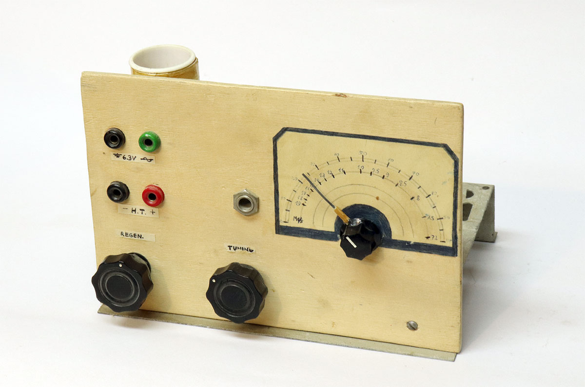
one. This simple regenerative receiver was my first self-made project, and was built from a construction article in “The young radio amateur”. Most of my following projects were self-designed, but these were early days. It served me well as a shortwave listener (4Z41055) until I saved up for a real communications receiver. The two-tube receiver is built in the then common “chassis and panel” construction. The chassis was sawn off from a longer one from a defunct home radio I’d salvaged, and the white plywood panel came from the cover of a shipping box that used to contain an olive oil tin. The hardest part of the construction was drilling holes in the chassis -- I recall trying to use a hammer and nail... as I said, I was new to this business. Inline voltage regulator module |
|
|
|
 Click a photo to enlarge |
|
|
|
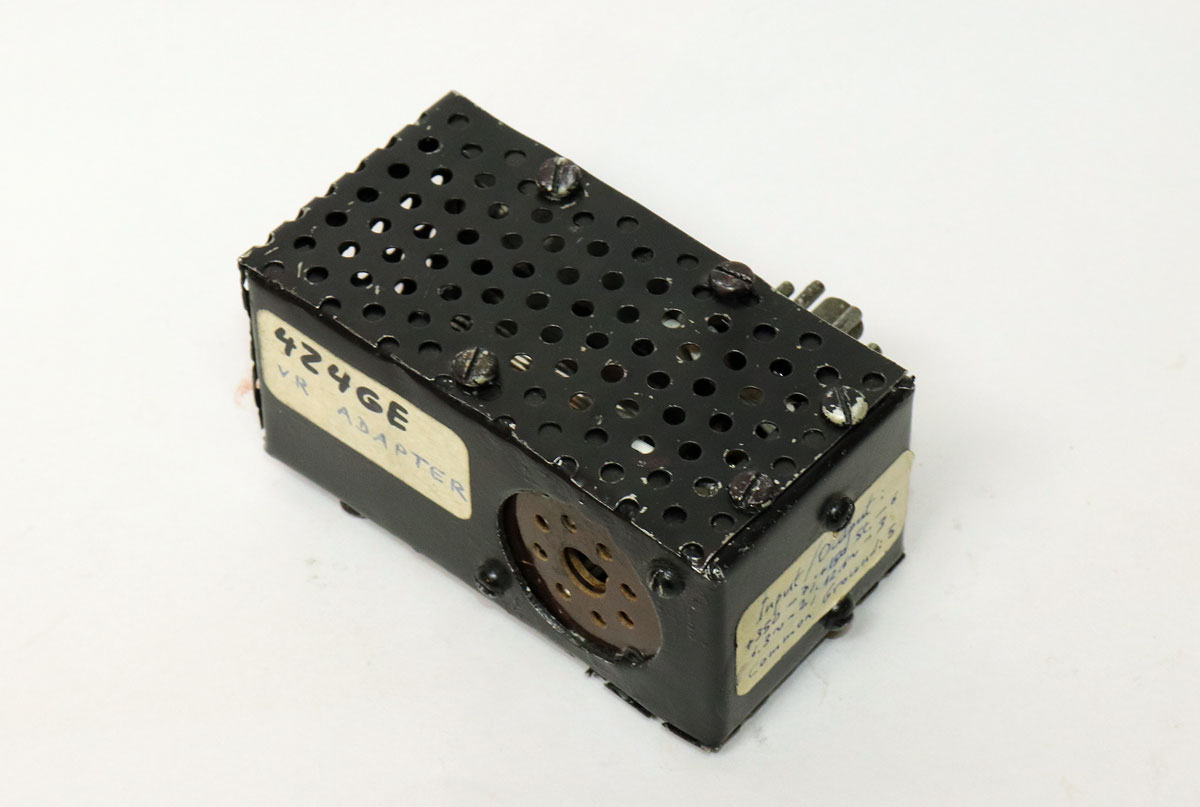
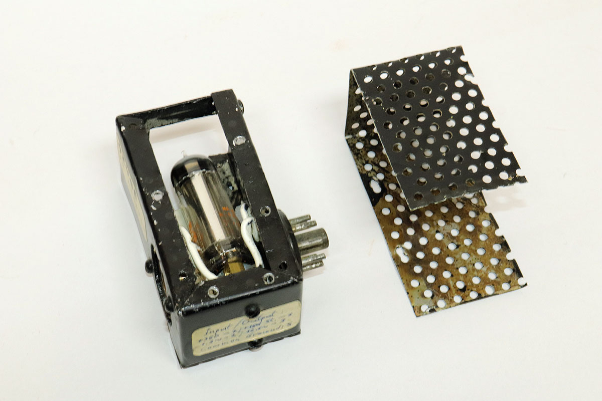
This weird device was probably my first
self-designed project. It is a feed-through voltage regulator: you
plug it into the output socket of a 350 volt DC unregulated power
supply and the socket at the opposite end provides 150 volt DC
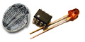
regulated (stabilized) power for experiments requiring it. I built this not too useful device because I was enamored of the “feed-through”, or inline, concept, and I enjoyed the challenge of making the thing as small as possible (those being vacuum tube days, this counted as quite small). The inside contained a miniature gas regulator tube and a power resistor; the enclosure was homemade, with the ventilated metal cover originating in a discarded automotive oil filter. Perforated sheet metal was a real challenge -- at that point I didn’t even have an electric drill... Balsa wood transistor tester |
|
|
|
 Click a photo to enlarge |
|
|
|
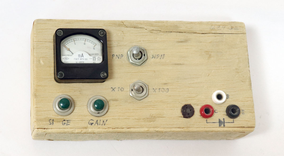
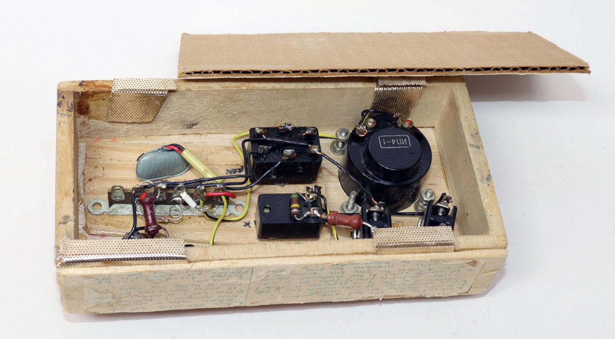
This simple tester for bipolar transistors was
built into a balsa wood box. This dubious design choice resulted
from the availability of that material as leftovers from a model
glider building class I’d attended, and the ease of cutting and
gluing it up. It also broke easily, as its condition attests. Oh
well... The meter and switches in this device came from a soviet field telephone that I managed to get my hands on -- this was after the Six Days war and such goodies were easy to come by. Come to think of it, this was my first piece of test gear. There would be many others. A kitchen timer |
|
|
|
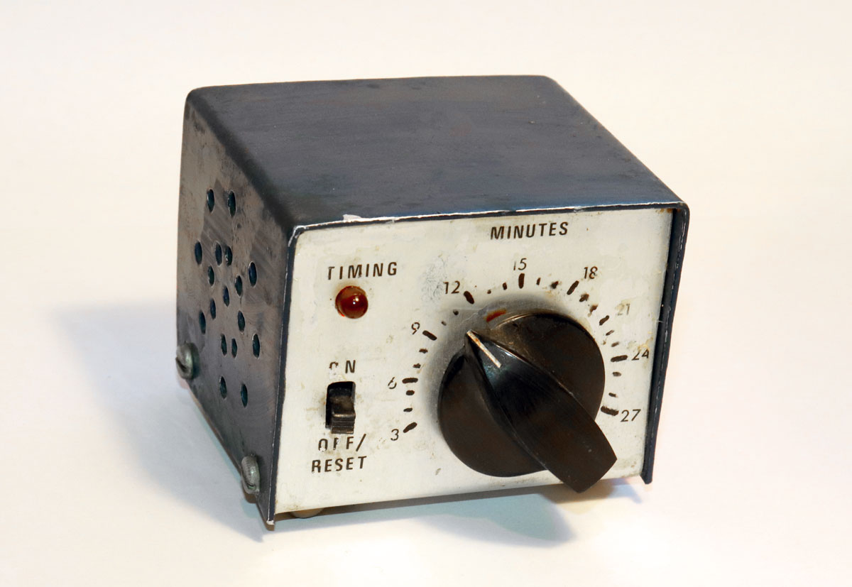
This device saw good use in our kitchen, and
shows the scars. It was compact, sturdy enough, and had a homemade
aluminum enclosure in a lovely dark blue/brushed aluminum color
scheme that I took a fancy to and went with in a number of following builds later on. I made a few of these timers, but only this one has survived. |
 Click photo to enlarge |
|
|
|
Homemade semi-automatic Morse key |
|
|
|
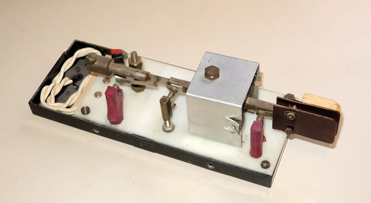
This semi-automatic key was based on a construction article in an old magazine. It is a simplified version of the commercial Vibroplex “Bug”, which was far beyond my budget back then. Like the Vibroplex, it makes dots automatically when the paddle is pushed one way, while the slower dashes are made manually by pushing it the other way. As you can see this was made from a strange mix of repurposed materials -- the paddle incorporates another piece of balsa wood from the same source mentioned above... |
 Click photo to enlarge |
|
|
|
Incidentally, I did buy the real Vibroplex
key recently, just to see it close up... and wow, its precision and
heft run circles around my version. Nevertheless, mine worked
remarkably well in my ham station. You can read more about this project here. Standing Wave Ratio meter |
|
|
|
 Click photo to enlarge |
|
|
|
 Click photo to enlarge |
|
|
|
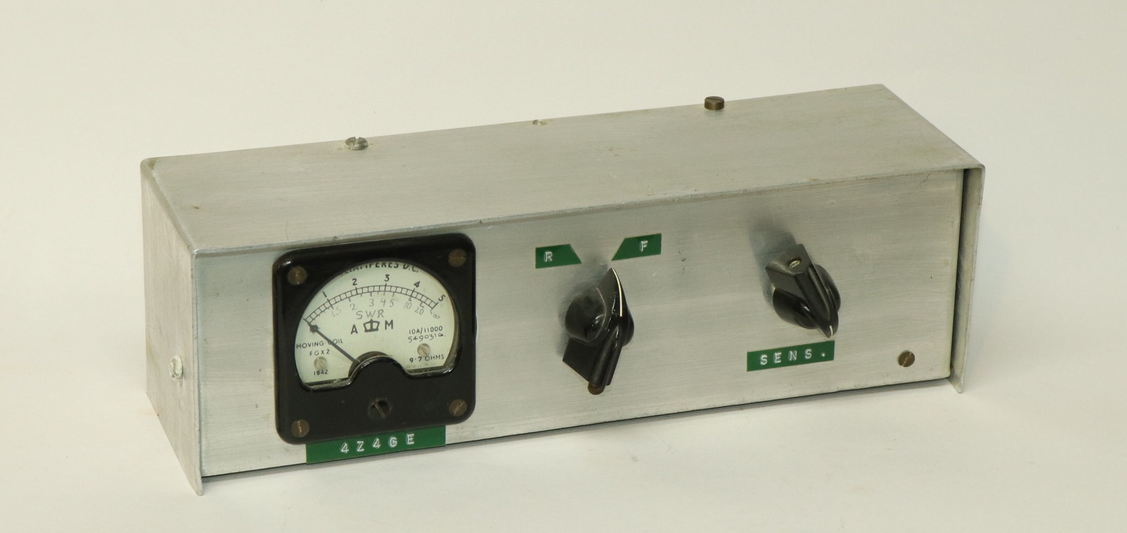
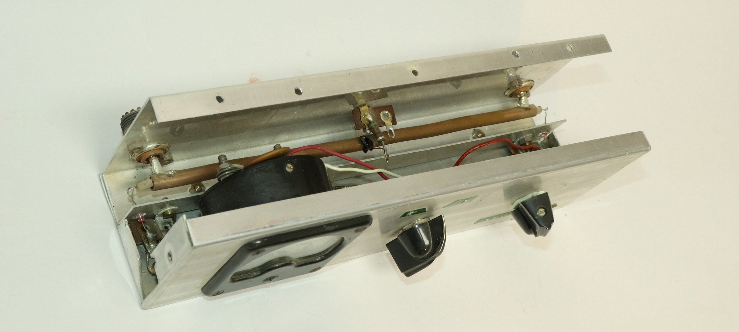
This is a “Monimatch”, a SWR meter which
connects permanently between the transmitter and antenna and
measures the forward and reflected waves of the signal coursing
between them. It is wonderfully simple -- the copper tube runs
between the input and output connectors, while the insulated wire
inside the tube sniffs the tiny signal needed to display the
measured quantities. This was built from an article in some ham radio publication -- I forget which. Grid Dip meter |
|
|
|
 Click photo to enlarge |
|
|
|
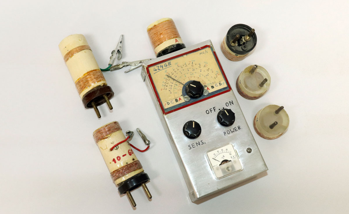
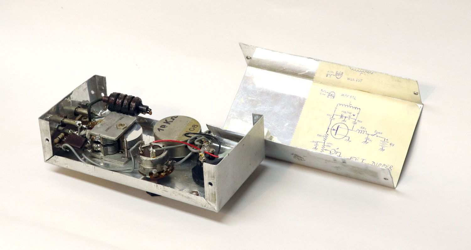
This Grid Dip oscillator played a key part in
my Radio Frequency gear development. In addition to its normal
function of checking the resonant frequency of L-C circuits, I made
it double as a capacitance meter, which was critical given that many
of the surplus capacitors I used -- especially the variable ones --
were unmarked. The trick was in the two long coils with the extra winding: the unknown capacitor hooked up to the alligator clips would complete a resonant circuit with the top coil, whose frequency would depend on the capacitor’s value; the scale on the instrument could thus be calibrated in capacitance. This was less precise than a commercial capacitance meter, but it was quite useful for my needs. The metal box was a homemade implementation of the “minibox” enclosures I saw in US electronics magazines, which I took a great liking to but could not find locally. Working the sheet metal was difficult because I was using tin shears to cut it and a pair of pliers to bend it to shape...
Mystery tester |
|
|
|
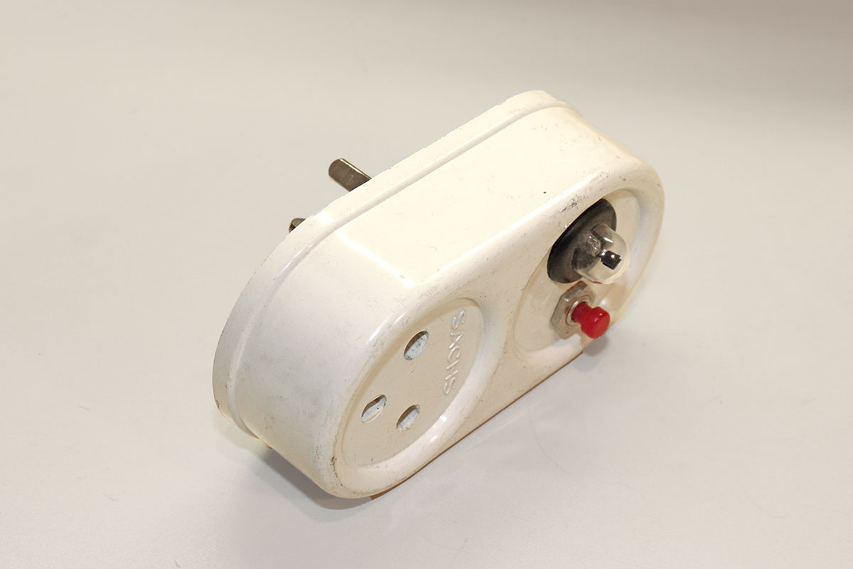
This gizmo is a bit of a mystery. Built into
a two-socket mains splitter, it allows you to plug it into a wall
outlet, then plug the power cord of an appliance into it, and push
the button. If the neon lamp lights up, it means the appliance
provides a resistive path from the live to the neutral. In other
words, say you plug in a toaster -- this thing can tell you whether
its heater element is broken. The mystery is, why on earth did I build it? What good could it do anyone, especially one with a multimeter at their disposal, which I certainly did have? Oh well, I must’ve enjoyed fitting it into the splitter -- remember, I used to love feed-through units... |
 Click photo to enlarge |
|
|
|
Experimental breadboard |
|
|
|
 Click photo to enlarge |
|
|
|
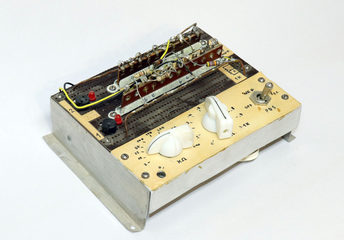
When I started experimenting with
transistors I built this homemade prototyping board, a hybrid of
perfboard and old style terminal strips. It provided power buses,
transistor sockets and some potentiometers that made soldered test
circuits much less messy. At some point I discovered solderless breadboards and this item fell out of use, but I remember it fondly nonetheless. Article card index |
|
|
|
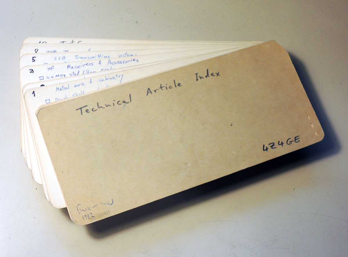
Back in my radio days I had a large library
of amateur radio and electronics literature: there were some volumes
of the ARRL Radio Amateur’s Handbook, a boxful of old issues of QST
that another amateur had donated to me, and the issues of Popular
Electronics, Electronics Illustrated, 73, and others that I would
buy at the local bookstore. These had a great many useful articles,
too many to remember, and I wanted to be able to find them. So I took a pile of blank IBM punch cards -- those were very available to me then -- and started a handwritten index in two parts: theory articles and construction articles, classified by subject. |
 Click photo to enlarge |
|
|
|
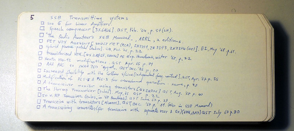
I shudder to think of the effort I
spent on keeping this updated... but I always did take my hobbies
seriously! Below is a card (one of many) devoted to construction category 5: SSB transmitter construction articles. |
|
|
|
 Click photo to enlarge |
|
|
|
Transistorized voltmeter |
|
|
|
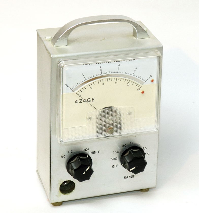
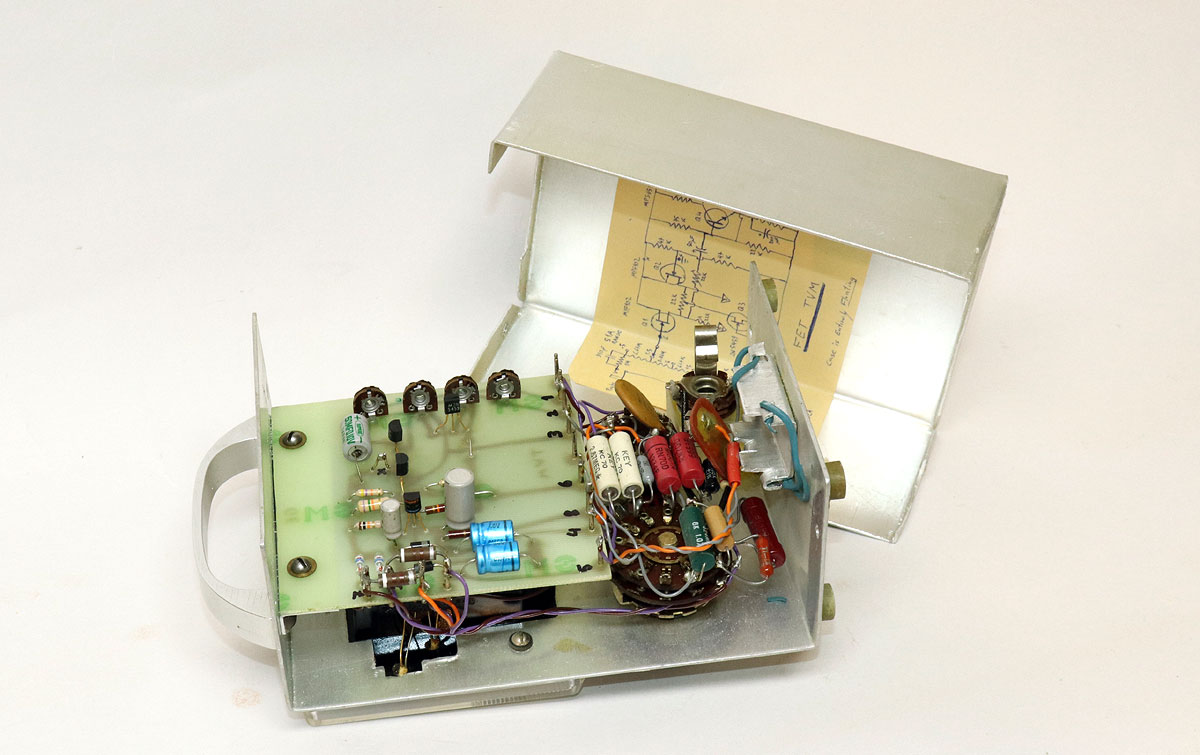
So here I was designing my own radio
equipment, and the only piece of measuring gear I had was the basic
multimeter I’d bought as a teenager. Small wonder that I started to
build various pieces of test equipment. This one is a TVM -- a
Transistorized Voltmeter, basically a VTVM with Field Effect
transistors instead of vacuum tubes. I used a panel meter scavenged
from something I’ve taken apart (I forget what), into which I added
the two red LEDs to indicate the scale being used -- a nice touch
absent in equivalent commercial units. The homemade enclosure, the home-etched circuit board and the overall construction are a far cry from the naïve workmanship evident in my earlier projects... clearly I was maturing in my construction skills. |
 Click photo to enlarge |
|
|
|
 Click photo to enlarge |
|
|
|
Circuit board etching bath |
|
|
|
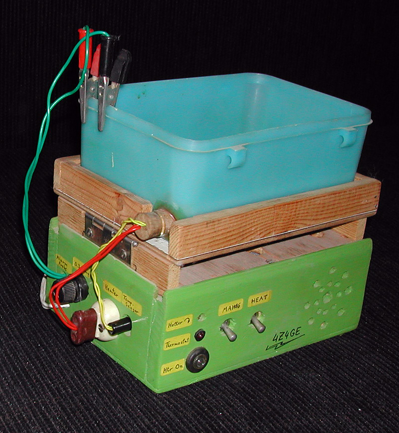
This contraption is a chemical bath for
etching circuit boards in Ferric Chloride solution. The solution had
to be heated and shaken to ensure proper etching, and I built this
to automate the process. It was built in a makeshift wooden box I
slapped together, and had multiple functions: it has a heating
element with a thermostat, it has a motor that tilts the etchant
tank up and down, and there is even a sensor to indicate when the
etch was complete -- when the two alligator clips that would attach
to the circuit board became electrically isolated. Not a thing of beauty, but it did the job quite effectively! |
 Click photo to enlarge |
|
|
|
SSB Transmitter |
|
|
|
 Click photo to enlarge |
|
|
|
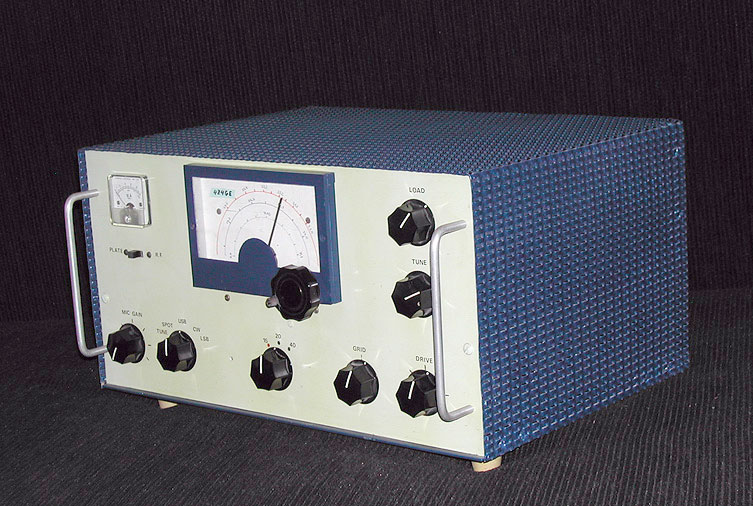
Here is my multi-band Single Sideband HF
transmitter, which replaced the CW rig I’d built as a novice (which,
sadly, I no longer have -- some of its components lived on in its
successor). It also incorporated surplus parts from two WW2 radios I
had on hand. This was my most ambitious project till then; it worked
quite well, enabling me to graduate from Morse code to voice
communications. You can read and see all the construction details here. Oscilloscope |
|
|
|
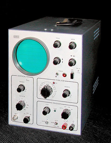
Another large project: A 10MHz triggered
sweep oscilloscope, possibly my toughest challenge, two years in the
making. Completely self developed, it started with a surplus cathode
ray tube and some circuit diagrams from CQ magazine, but when those
failed to meet my needs I bought a modern CRT and developed my own
circuits. Also my first serious all-solid-state project, and the
first based on new rather than surplus components (well, except the
screen bezel which was reworked from a cookie jar lid). I found that an oscilloscope is a very unforgiving project to develop, because any mistakes -- even the slightest spurious signal -- show up directly in the waveforms on the screen! |
 Click photo to enlarge |
|
|
|
Function generator |
|
|
|
 Click photo to enlarge |
|
|
|
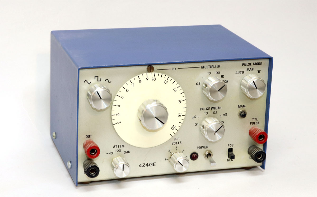
Probably my prettiest piece of lab gear, I
designed this function generator around the newly released 8038
chip. As the aluminum enclosures of this and the oscilloscope show, by that time I was no longer bending metal with a pair of pliers; in fact I’d built a sheet metal bending machine, a poor relative of the one I saw in the university’s machine shop. Mine was made of hinged wooden plates rather than heavy steel, but it sufficed. Anti-toddler alarm |
|
|
|
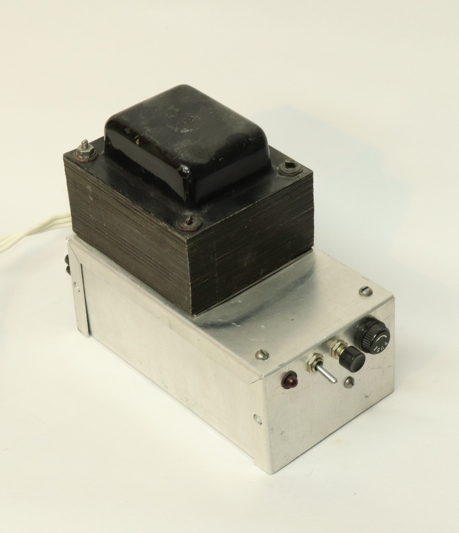
This was a success and a failure: a system to
raise an alarm when my young son went into my den, where he’d
gleefully attack my lab bench. It used two infrared beams at
different heights across the door, to check for adult accompaniment,
and would cackle like a hen if a toddler went in alone (most of the
circuit was the cackle synthesizer, which did a very credible job).
The big transformer was an anachronism and an overkill, but it was
available in my junk box so I pressed it into use. After much tinkering I installed the sensors on the doorframe, and everything worked fine for a few hours. Later in the same day the kid discovered these wonderful mysterious additions to the doorframe and kicked them right off... |
 Click photo to enlarge |
|
|
|
Image scanner for the Commodore 64 |
|
|
|
 Click photo to enlarge |
|
|
|
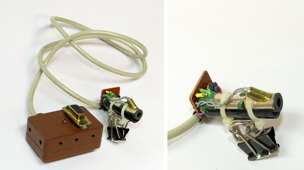
This strange device is an optical scanning
head for a Gemini 10X dot matrix printer. You clip it to the print
head so the lens in the brass tube can focus light from the paper
onto a phototransistor at the back; the signal is processed in the
brown box and fed to the analog paddle input of a Commodore 64
computer! This was the hardware end of my effort to do digital image processing on the Commodore. The software end involved developing a long assembly language program (assembler being necessary for speed). This fun project actually worked, within the limits of the C64’s resources, and you can see some examples of the results here. Optical Bench |
|
|
|
 Click photo to enlarge |
|
|
|
This is a test bed for experimenting with
optoelectronic systems. I built it to mount the components -- light
sources, lenses and photodetectors -- that I needed to optimize for
systems like the anti-toddler alarm and the scanner described above.
A far cry in size and precision from the optical benches I’ve used
when studying for my electro-optics degree, but I must say it served
its purpose well enough. The system mounted on it in this photo
must’ve been a prototype of... something, but I can’t recall what.Theremin |
|
|
|
 Click a photo to enlarge |
|
|
|
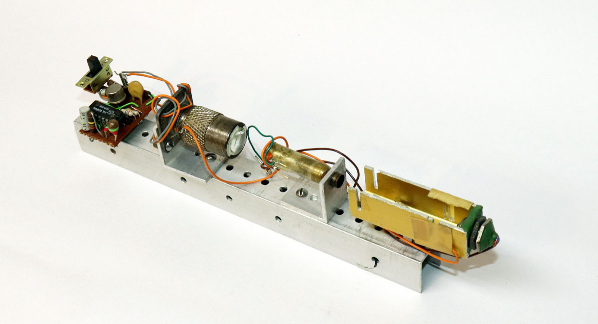
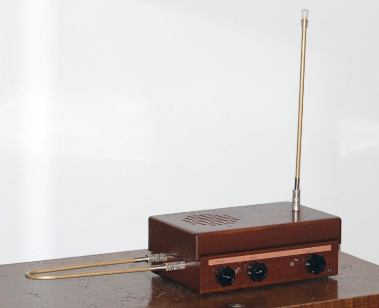
My last electronics construction project,
decades after the rest: my brother, who is a musician, had been
asking for it for years, so I finally decided to build him a
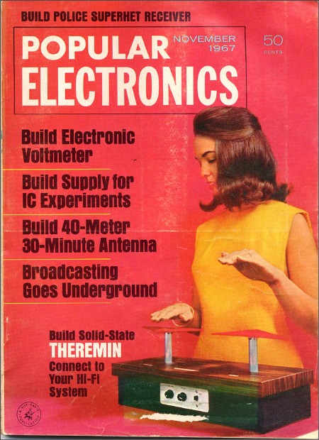
Theremin. I chose to use a design from a vintage Popular
Electronics magazine that I had, the November 1967 issue. This
required me to shop on eBay for the obsolete transistors in the
schematic, and to revive my circuit layout and soldering skills...
and while the result wouldn’t be a match for a commercial version,
it did emit the wailing sounds that an unpracticed player could hope
for. The two antennas were shaped from the remaining rods of the
salvaged TV antenna that had given my SSB transmitter its front
handles, 45 years earlier... That’s all, folks... lots of
diverse projects, some more useful than others, but all fun to
build. And on rereading what I wrote here, I notice the repetition
of statements like “This was less precise than a commercial
capacitance meter, but it was quite useful for my needs.”, or “Not a thing of
beauty, but it did the job quite effectively”, and so on. I like
that, because while I enjoyed the challenges of building all this
stuff, the ultimate objective was to obtain through my own
skills tools that I might not have had access to otherwise. Wayda go! |
|
|
|
|
|
|
|
Home | HOC | Fractals | Miscellany | About | Contact Copyright © 2024 N. Zeldes. All rights reserved. |
|