 Home
Home
 Up
Up
|
|
|

|
The Professor’s calculator |
|
|
|
|
|
|
Here we have a calculator devised by Professor R.H. Smith at the very end of the 19th century. It is a long-scale logarithmic slide rule, and uses a helical layout of the scale to achieve the sweet spot of high precision in a manageably small instrument. |
|
|
|
 Click photo to enlarge |
|
|
|
 Click photo to enlarge |
|
|
|
Like the larger and well-known
Fuller
calculator, and like Lafay’s little known
Hélice a Calcul,
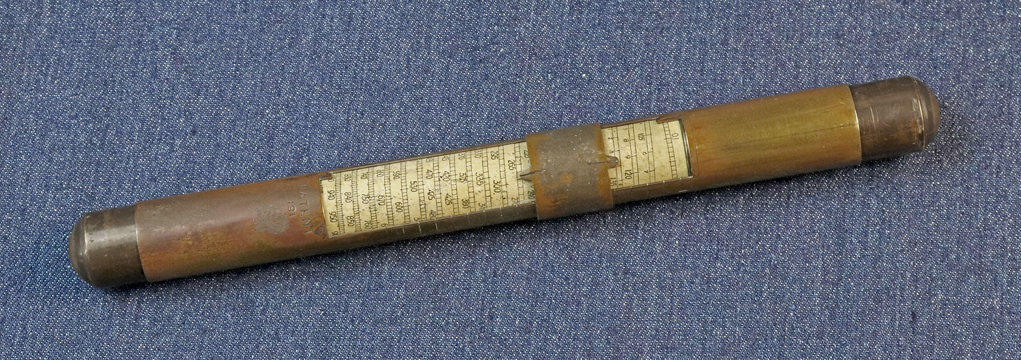
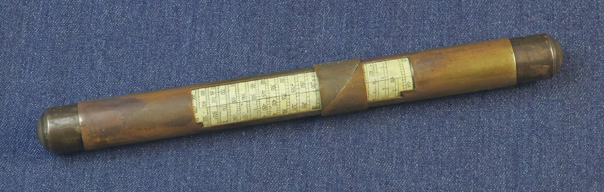
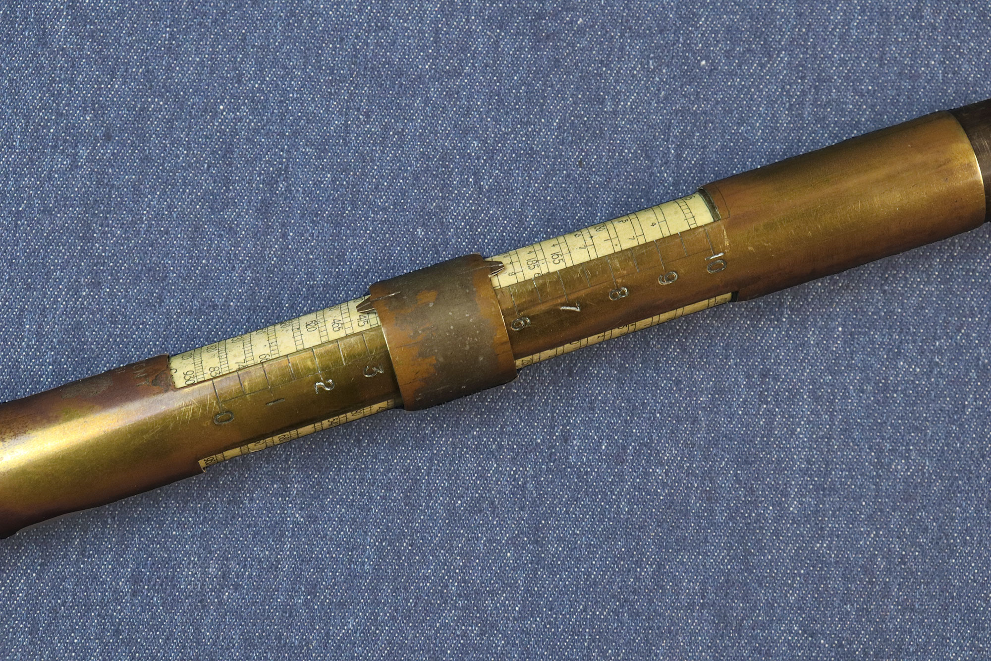
the R. H. Smith involves two elements: a very long logarithmic scale
that is wound tightly around a much shorter cylinder, and two
independently movable indicators that can be set to two numbers on
the scale, then moved as one to a new position to indicate a result.
The instrument is made of three metal tubes (my guess is brass, whose yellow color is visible where an outer coppery layer wore out). The inner tube carries the logarithmic scale; the second tube slides over the scale, exposing it through two large cutouts; and the third tube is really a narrow ring that can be moved over the second tube. There are actually six pointers to choose from, two at corners of each cutout and two at the edges of the ring. The length of the instrument is about 24 cm, and its diameter at the outermost ring is 2.4 cm. The scale is 2.05 cm in diameter and has 20 turns, so the scale length is a little over 128 cm. At the top of the scale is a linear scale running from 0 to 0.05, and along one of the cutouts is a linear scale of 0 to 10 in units of 0.5 which corresponds to the turns of the spiral. These features are used to calculate the logarithm of any number on the spiral. |
|
|
|
 Click a photo to enlarge |
|
|
|
Smith was granted
British patent No. 17,357
on Nov. 4, 1899. The patent is titled “Improvements in Logarithmic
Calculating Instruments”, and in it Smith repeatedly emphasizes the
advantages his calculator has over competing devices. This can give
us interesting glimpses into his thought process as he made his
design decisions. For example: Throughout the central part of its length upon which the scale is placed, it is made of slightly less outside diameter than at either end. Thus the second tube which fits these ends does not rub upon the scale so as to abrade or dirty its surface. Very, very clever! I can see the advantage of this, because my Fuller calculator has some serious abrasion on its shellacked paper scale from rubbing by the flexible metal cursors it uses. Then there is: The three tubes being made of the same material, preferably of thin metal, change of temperature or the like influence produces equal expansion or contraction in all three so that such change does not produce either slackness or tightness in the fit of one upon the other tube with consequent easy sliding without shake or side-play at all times. This result is obtained without the use of felt or other soft packing between the tubes such as has been required in other similar instruments. Amen to that. After 120 years, the tubes – though tightly fit to each other without any padding – slide fairly easily. The jab at the Fuller device, which does rely on felt, is unmistakable. |
|
|
|
There was also what appears to be an earlier R.H. Smith calculator, which I don’t have. This model, which uses the same concept as the Fuller calculator, looks flimsier and prone to damage, and may be the reason for this paragraph in the patent: |
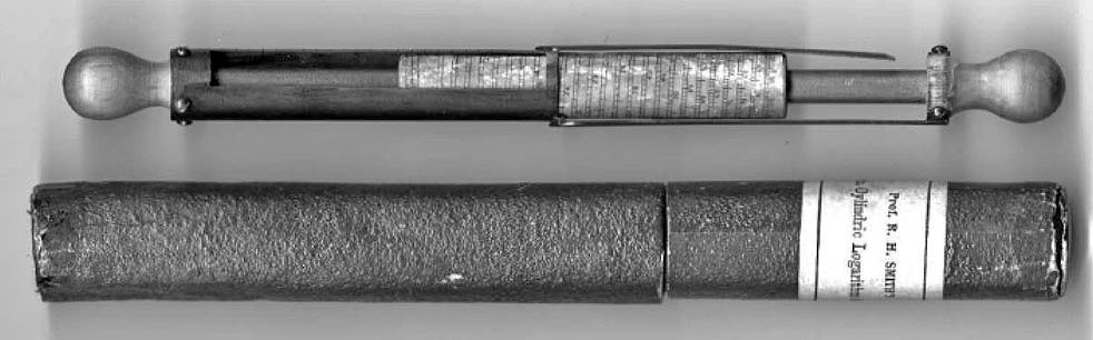 Click photo to enlarge Photo credit: D. Weinstock (see reference below) |
|
|
|
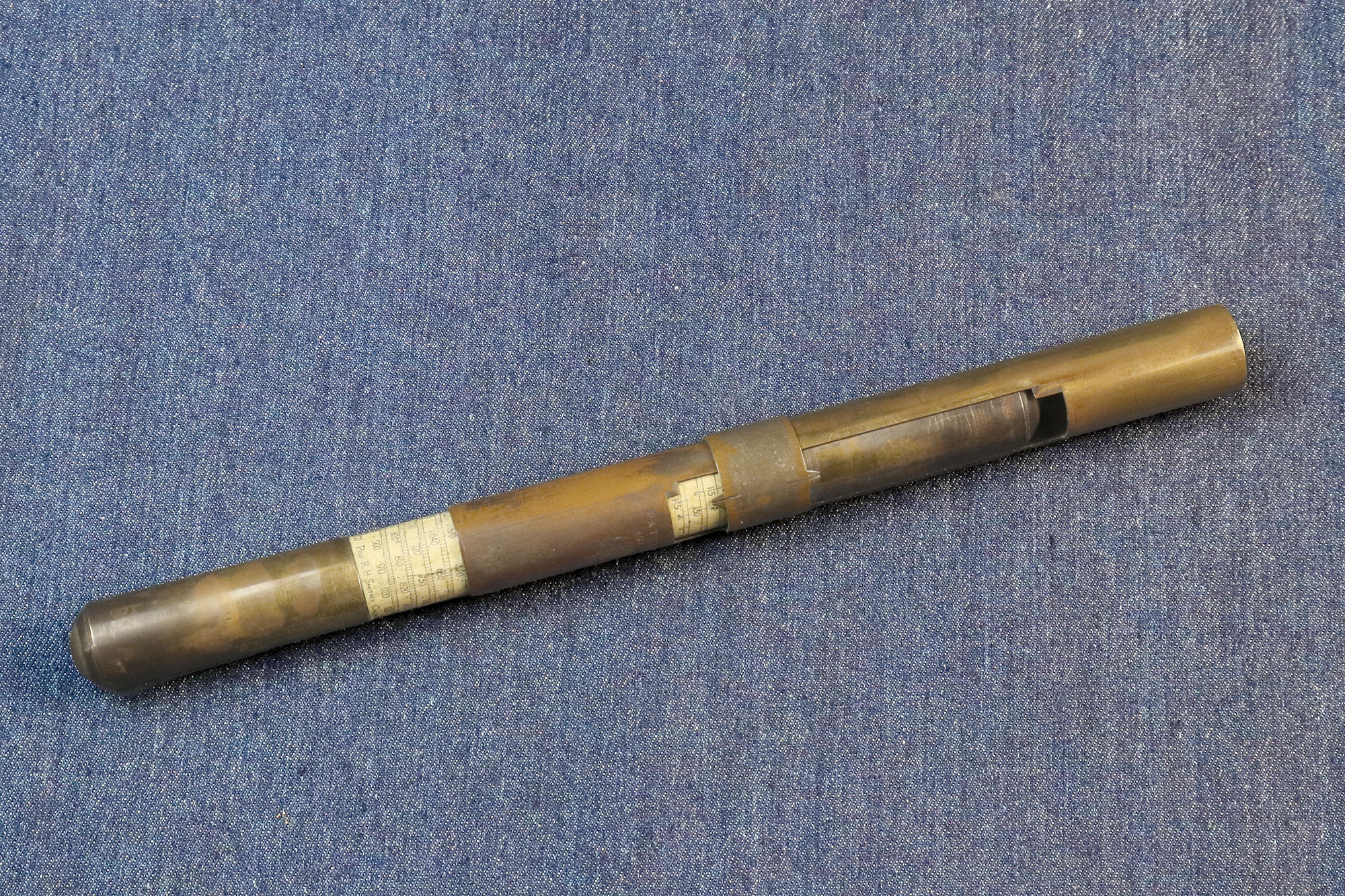
These reading indices are thus placed upon and attached to the tube which carries them in a very rigid manner without overhanging or springy parts so that the pairs of indices cannot be sprung or bent out of their correct relative positions and so that no adjusting device for drawing them from time to time into true relative position is necessary. This arrangement of tubes without overhanging or projecting parts also obviates the risk of such parts catching each other or the dress or fingers of the operator when being moved past each other in the process of manipulation, whereby they are, in other similar instruments, frequently bent out of shape. Clearly the good professor had been burned by the “overhanging or springy parts” of the earlier device he’d built, and rightly considers the later model to be an improvement. Indeed, I was impressed by the solidity of the latter: it is as firm and robust as a wooden rod. Just compare the photo below with the one of the earlier model above. |
|
|
|
 Click photo to enlarge |
|
|
|
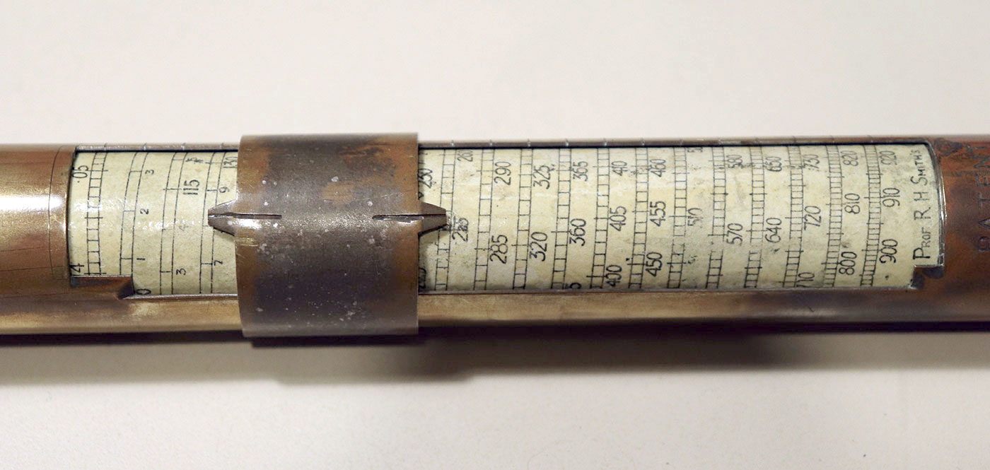
Lastly, the patent also says: The instrument being composed of these three parts is called the Ring-Holder-Scale Logarithmic Calculator, or more shortly the R-H-S log rule, this name being a mnemonic materially assisting the recollection of the correct manipulation of the instrument. Not really needed, but obviously Smith couldn’t resist this wordplay on the his own initials! We know from the patent that our inventor was Robert Henry Smith, “Civil and Mechanical Engineer, of Ellerslie, Brunswick Road, Sutton, in the County of Surrey”. There is no mention of a professorship, and we only learn of that because the instrument itself bears the legend “Prof R H Smith’s calculator” at the bottom of the scale. As an engineer, I’m pleased that he chose to identify himself to the patent office by this vocation rather than by the academic title... |
|
|
|
Exhibit provenance: Bought from a British antiques merchant. More info: The RHS calculator, by Daniel Weinstock, M.D., in the Journal of the Oughtred Society, Vol. 6, No. 2, Fall 1997 pp. 11-12. |
|
|
|
|
|
|
|
Home | HOC | Fractals | Miscellany | About | Contact Copyright © 2022 N. Zeldes. All rights reserved. |
|