 |
 Home
Home
 Up
Up
|
|
|

|
A homebrew Single Sideband transmitter |
|
|
|
|
|
|
I got my ham radio license in high school, in
1969, and it took me no time to cobble together a single-tube CW
transmitter and start communicating with radio amateurs around the
world. By the time I was in university I felt I should move on to
voice communication, and decided to skip AM and go straight to SSB
(for the muggles among you, CW is Morse code, whereas SSB -- Single
Sideband -- is a voice transmission technology). Getting there took
me most of 1974, because I had to design and build a rather complex
transmitter under difficult constraints. Not only was I on a very
tight budget, but Israel at the time was not the hi-tech hub that it
is today, so I had to scrounge for most of the parts in old radios
(WW2 military surplus gear was especially useful there) and work
around the missing pieces by improvising (I write more about that
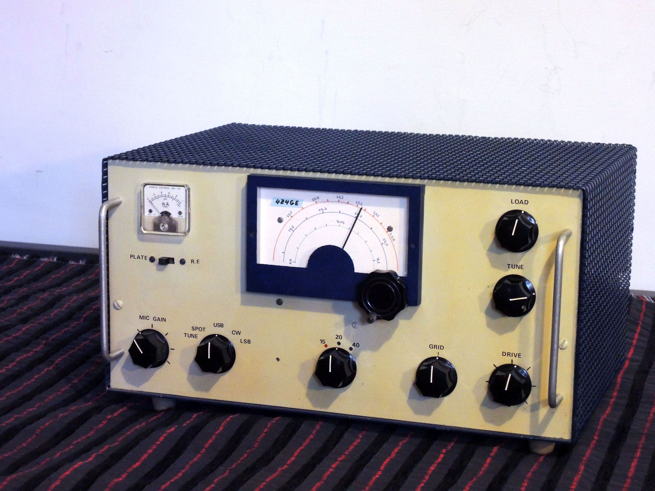
here). This was the last tube-based DIY project I undertook before I switched to solid-state; and the most challenging. In this article I share some of the arcane design and construction details. If you are not a geek, you may want to look elsewhere on this site... Here is the finished product, which had served me well for a few years. The enclosure is homemade -- I actually built me a homemade sheet metal bending machine to produce homemade equipment boxes. The two handles on the panel were quite unnecessary, but I thought they’d look cool; I formed them from the rods of a broken TV antenna. |
|
|
|
 Click photo to enlarge |
|
|
|
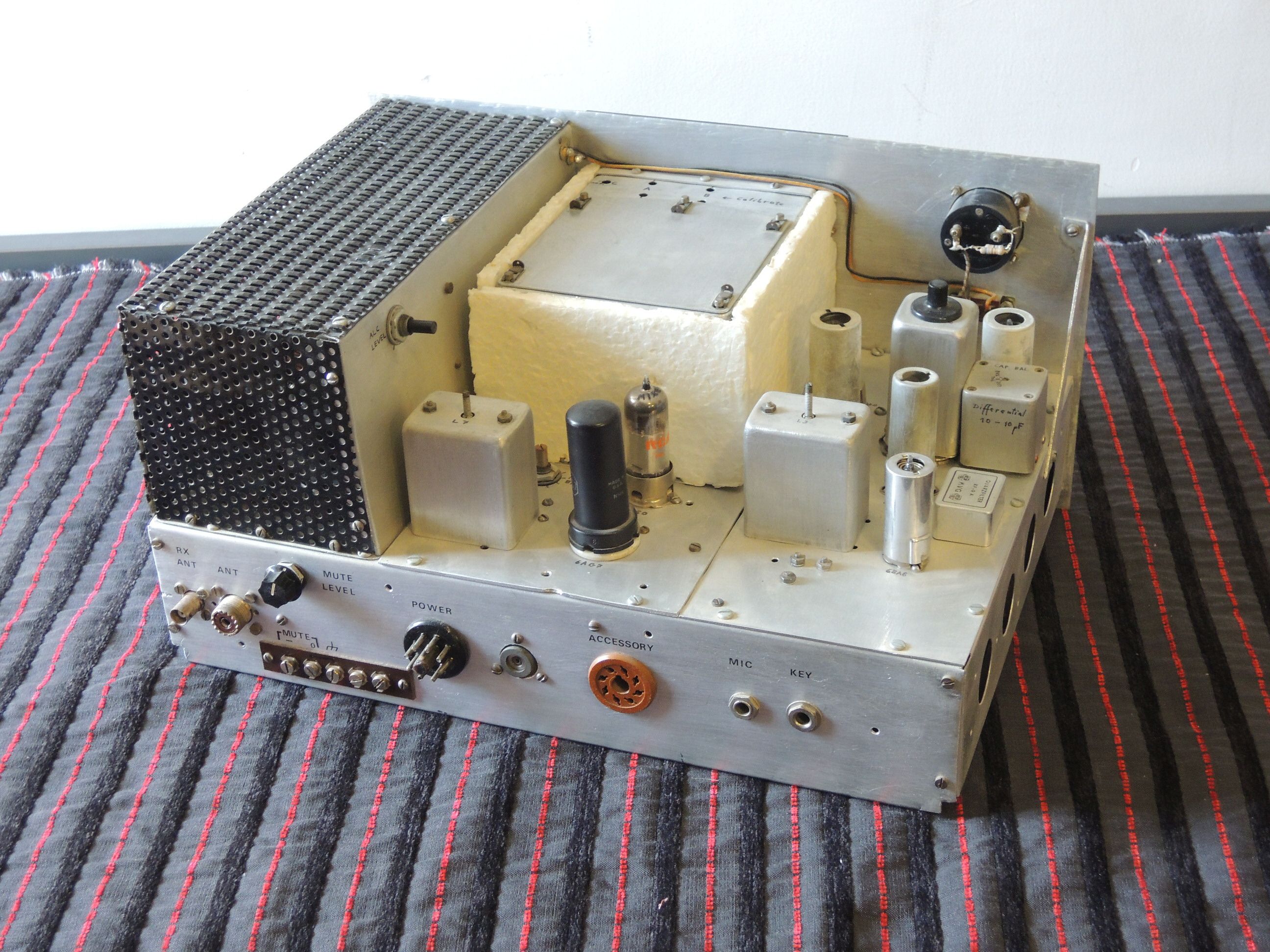
Here is an inside view from the back. The power amplifier tubes needed ventilation as well as shielding; that was always a challenge because I had no good source of perforated metal. The black sheet with the round holes actually came from the cover of a car air filter that I found in the trash. |
|
|
|
 Click photo to enlarge |
|
|
|
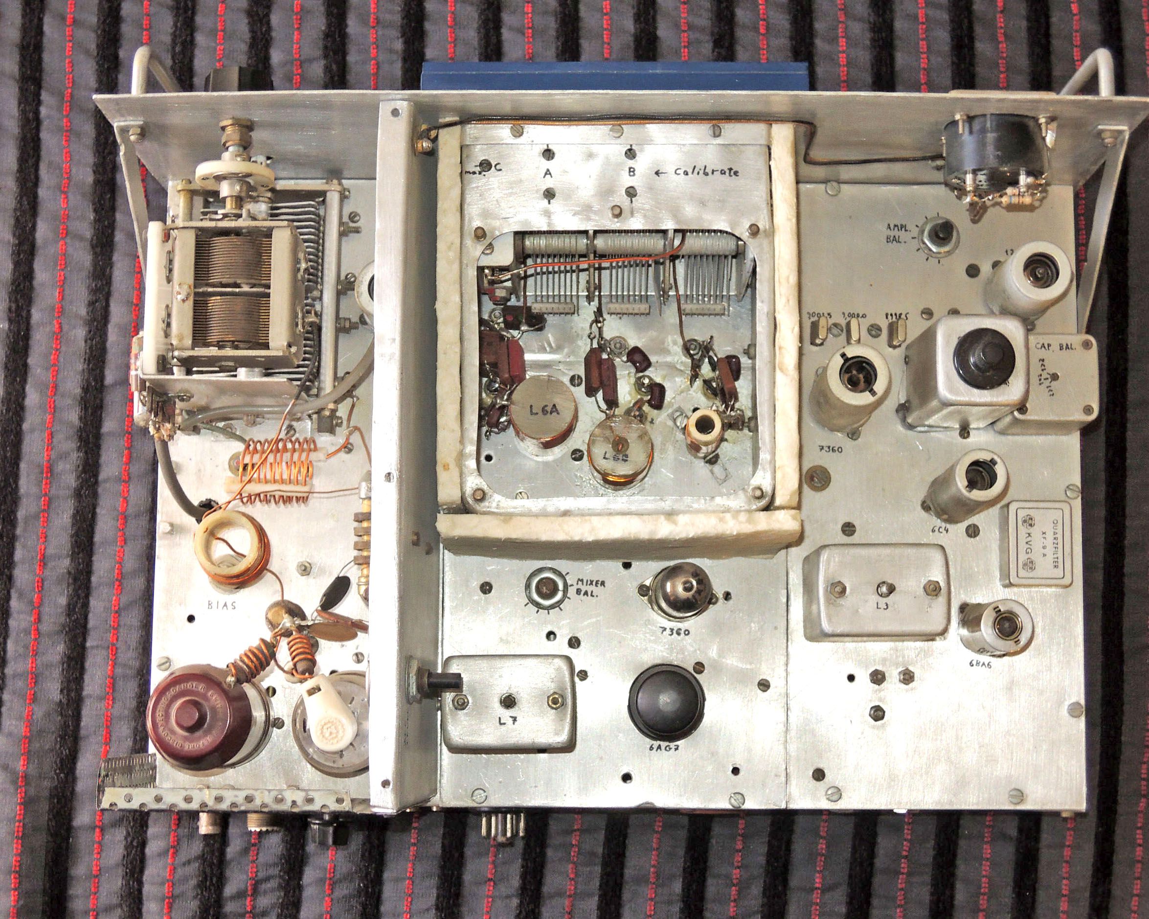
Top view with shielding covers removed. The transmitter was built from three separate modules -- the SSB generator on the right of the photo, the frequency converter in the center, and the power amplifier on the left; each was built on a flat aluminum plate that could be assembled onto the main chassis frame when it was finished. |
|
|
|
 Click photo to enlarge |
|
|
|
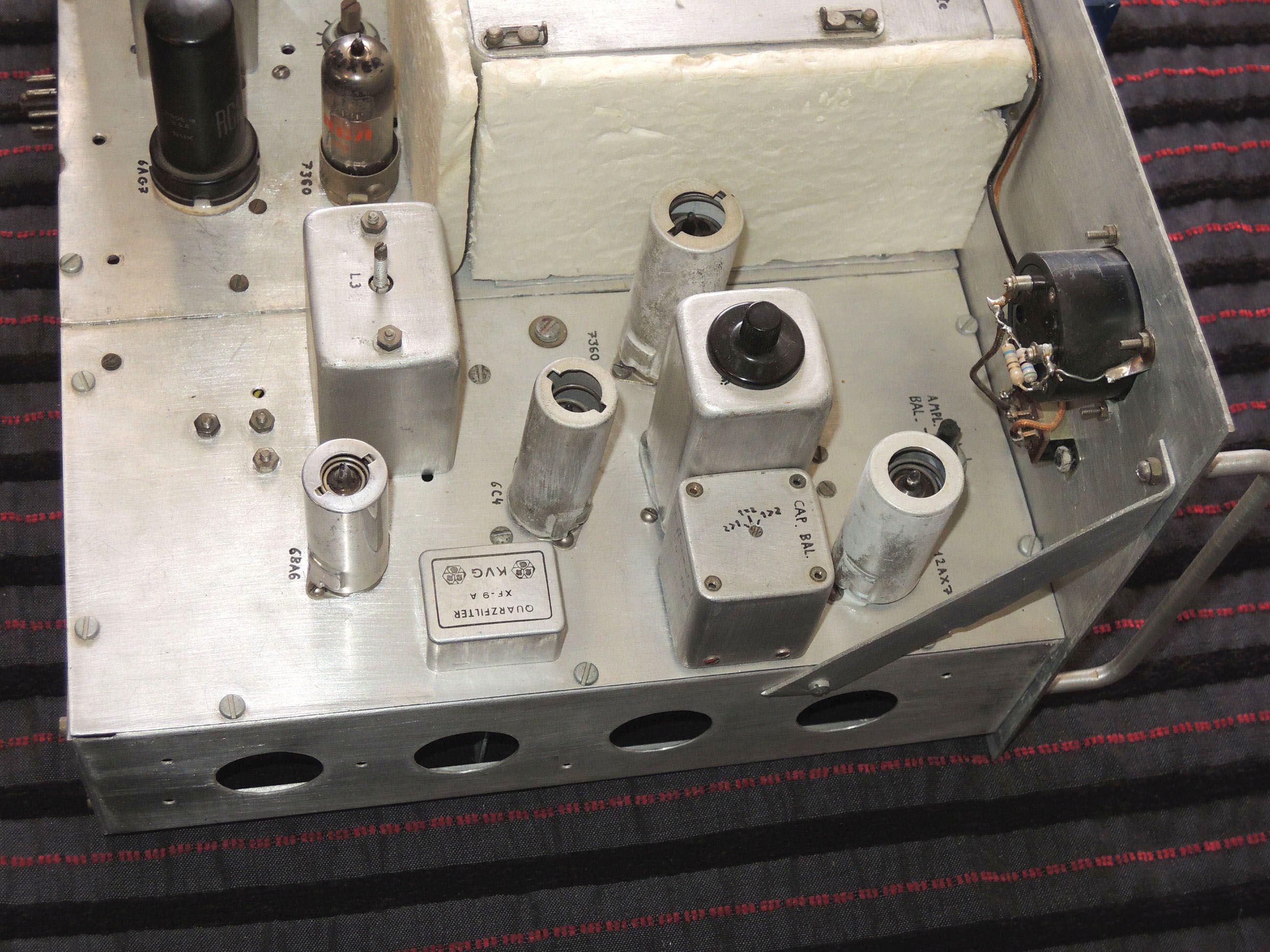
The SSB generator module. This part of the
circuit was roughly modeled on an article in the 1970 ARRL SSB
manual, and used the 7360 beam deflection tube as a balanced
modulator at 9 MHz. A crystal filter eliminated the unwanted
sideband and the result was amplified by a 6BA6 and sent to the
mixer in the converter module. The crystal filter was one crucial component I had to buy new. It was unavailable locally, so I had my uncle get it for me when he traveled to the US. The other tuned circuits in the square metal cans were all repurposed from various surplus military radios. |
|
|
|
 Click photo to enlarge |
|
|
|
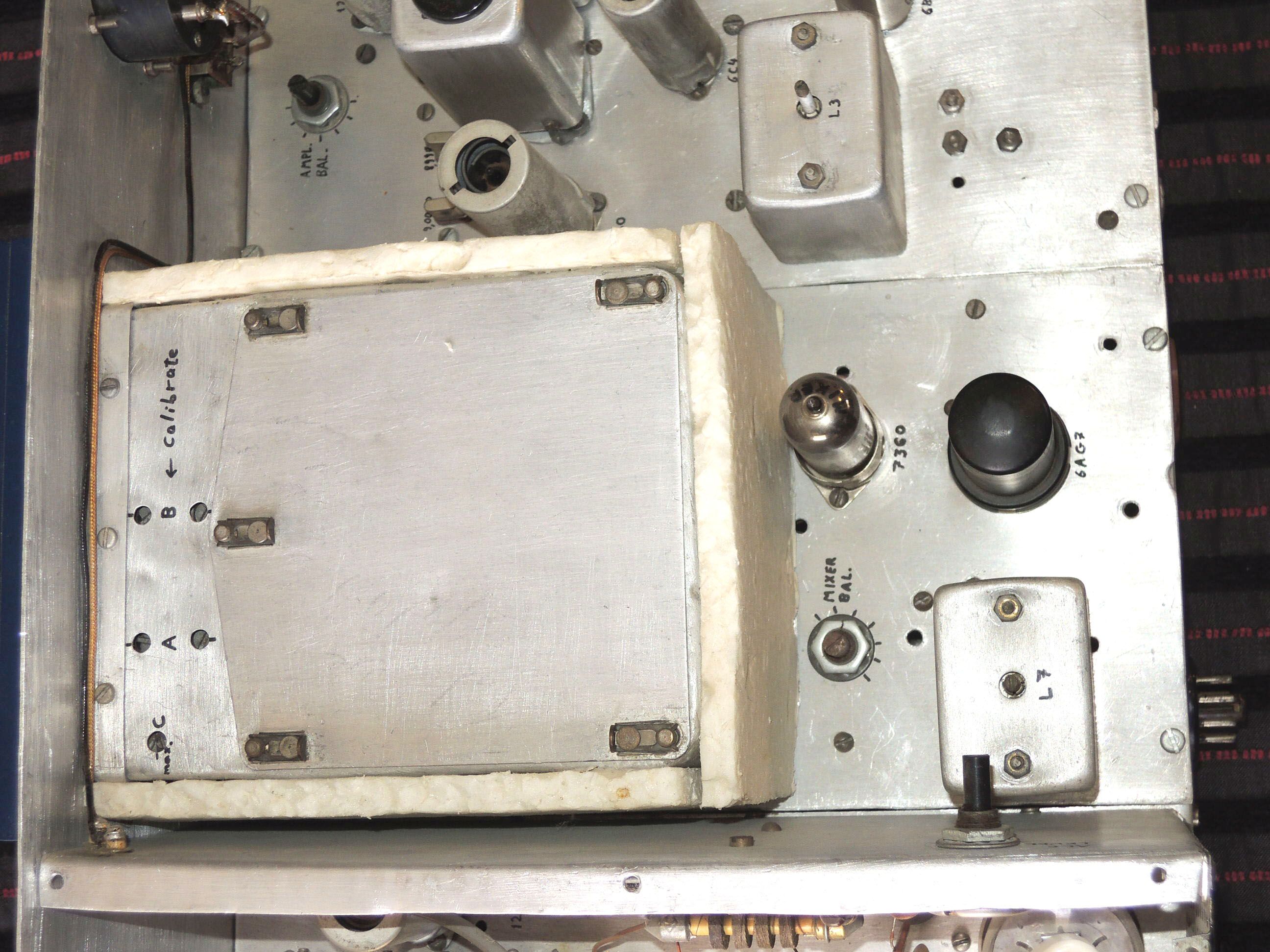
Next, the converter module. The trusty 6AG7
in its tall black metal envelope is the VFO, while a 7360 is used as
a balanced mixer to convert the 9 MHz signal to the selected amateur
band frequency. The shield box with the clip-on cover was cannibalized from the enclosure of the handy ARC-5 aircraft receiver, which was a common item in the military surplus market. The Styrofoam layer was added after I wasted two months hunting down a minute frequency drift caused by an unstable fixed capacitor; I decided that heat-insulating the tuning tank couldn’t hurt. |
|
|
|
 Click photo to enlarge |
|
|
|
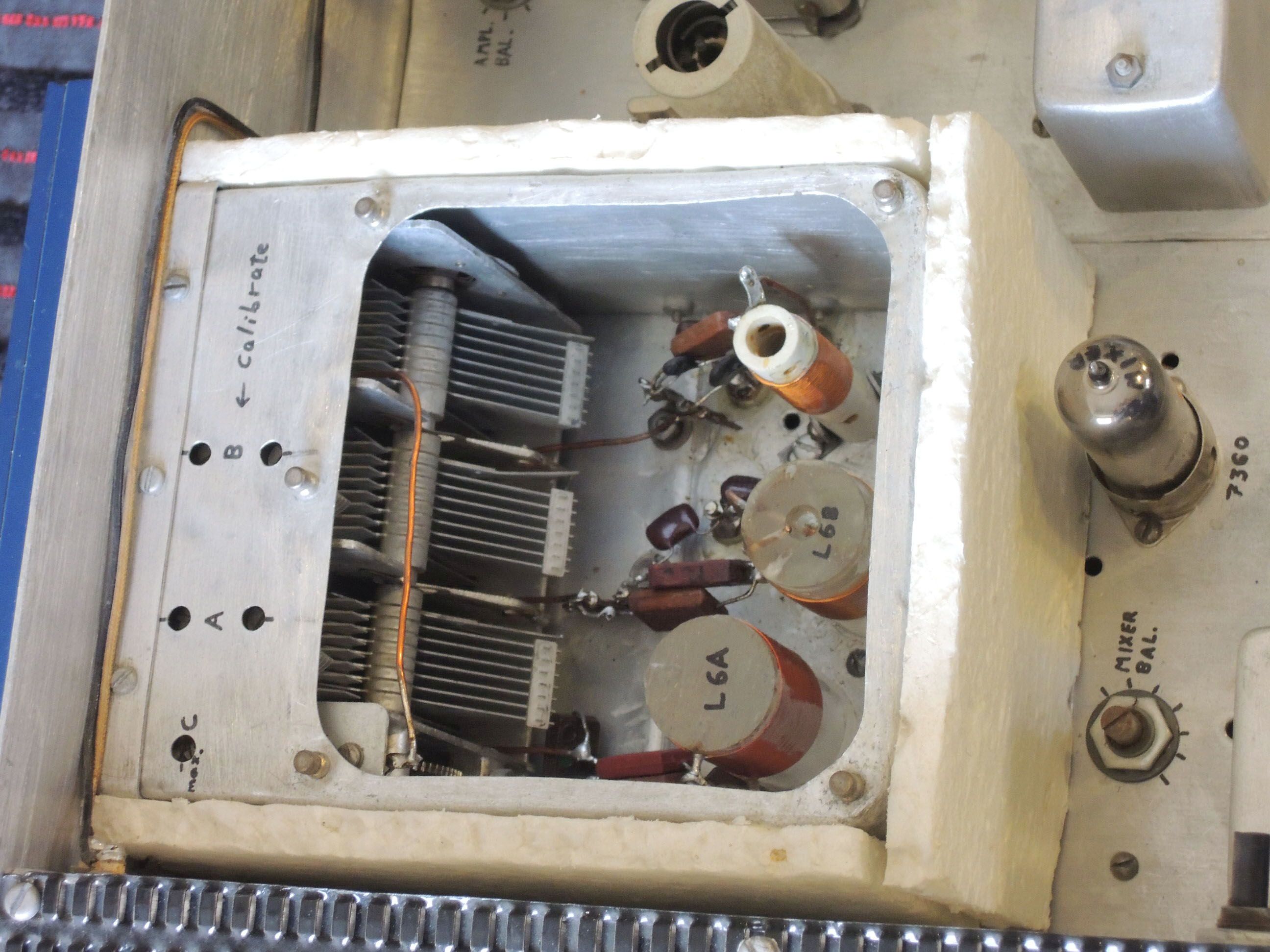
Here we have the VFO tuning compartment with
cover off. The 3-gang variable capacitor is also from the ARC-5 and
has an excellent built-in reduction gear that I put to good use. I was reluctant to build one fixed band VFO and separate converters for each ham band, so instead I implemented a separate tuning tank for each band, assigning one section of the variable capacitor and all the related coils and trimmers to each band, and using a massive band switch to connect the correct tank -- as well as other band-dependent components further down the line -- according to the selected band. Definitely not the textbook solution, but it worked and kept the tube count down. |
|
|
|
 Click photo to enlarge |
|
|
|
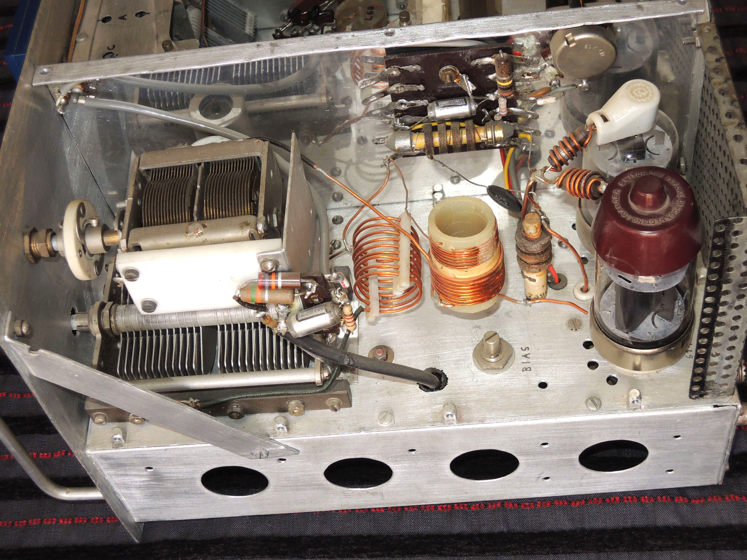
This is the power amplifier module. It used two 6146B power beam tetrodes, one recycled from my earlier CW-only transmitter and another retrofitted later to add power. The inductors are of course manually wound on a variety of homemade forms. |
|
|
|
 Click photo to enlarge |
|
|
|
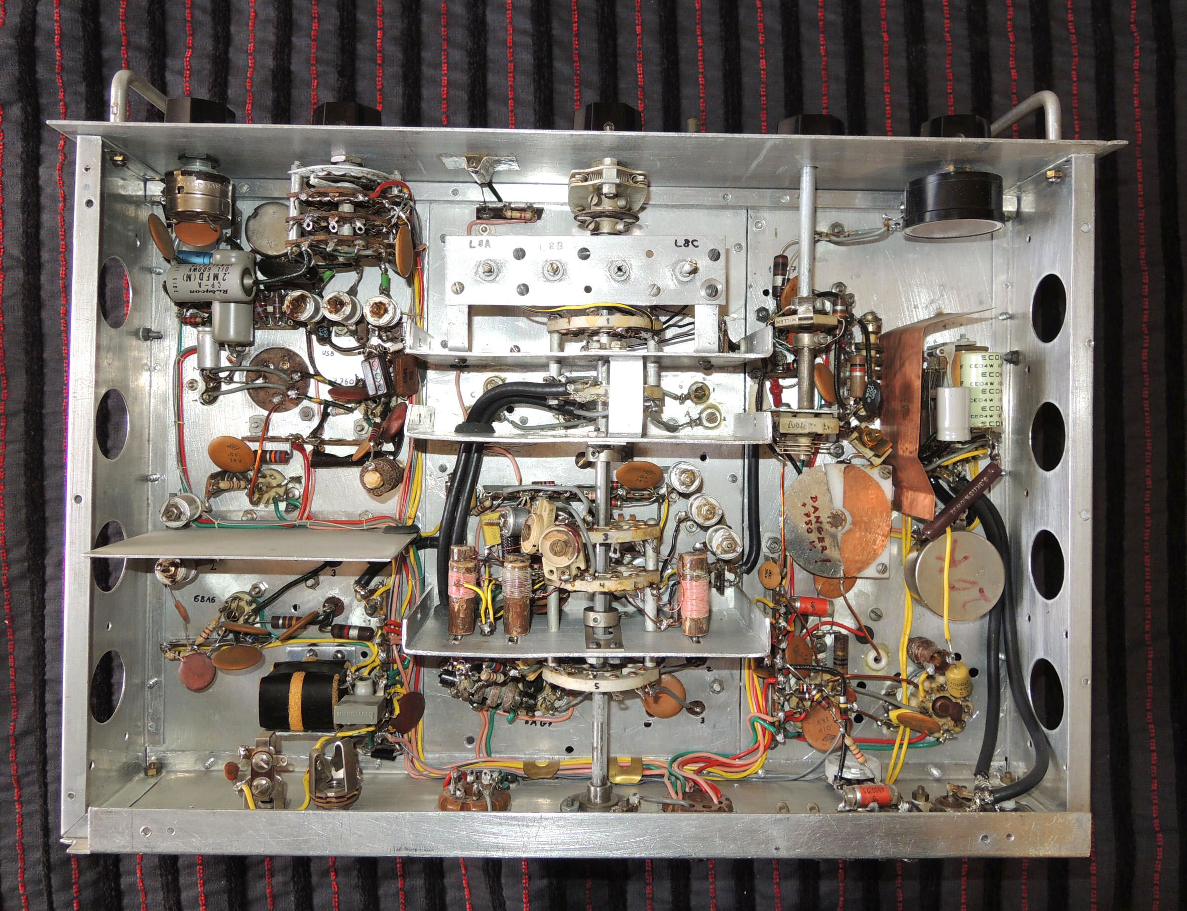
The underside of the chassis, with the SSB generator on the left and the power amplifier on the right. The shielding in the central converter module is for the coils and their switch. |
|
|
|
 Click photo to enlarge |
|
|
|
And here is the view with the converter module’s shielding off. The shaft going down the middle runs from the band-switching knob on the front panel all the way to a bearing on the opposite wall; on the way it operates five ceramic sections that form a 10-pole rotary switch. This is a heavy-duty switch -- it came from a huge BC-1147 WW2 receiver I’d won in a sweepstakes of the Israel Amateur Radio Club. Lots of shielding partitions keep out undesired coupling and noise (you can never have too much shielding...). |
|
|
|
 Click photo to enlarge |
|
|
|
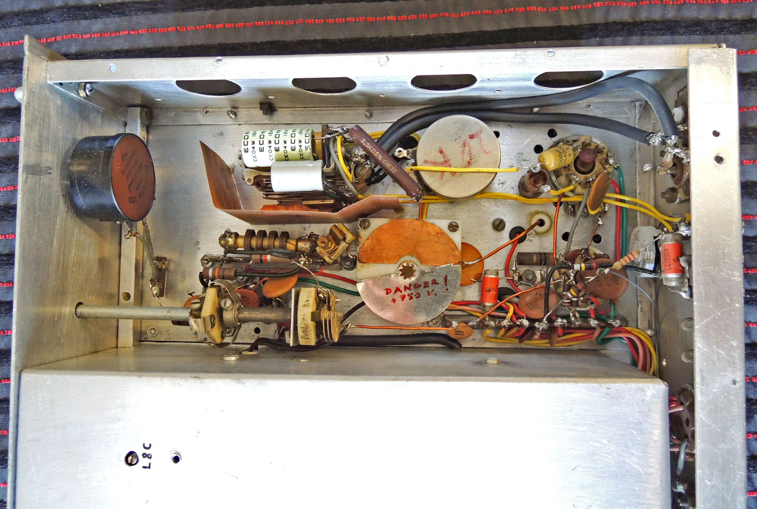
Bottom view of the Power Amplifier. The funny part with the red alert is a homemade variable neutralizing capacitor. |
|
|
|
 Click photo to enlarge |
|
|
|
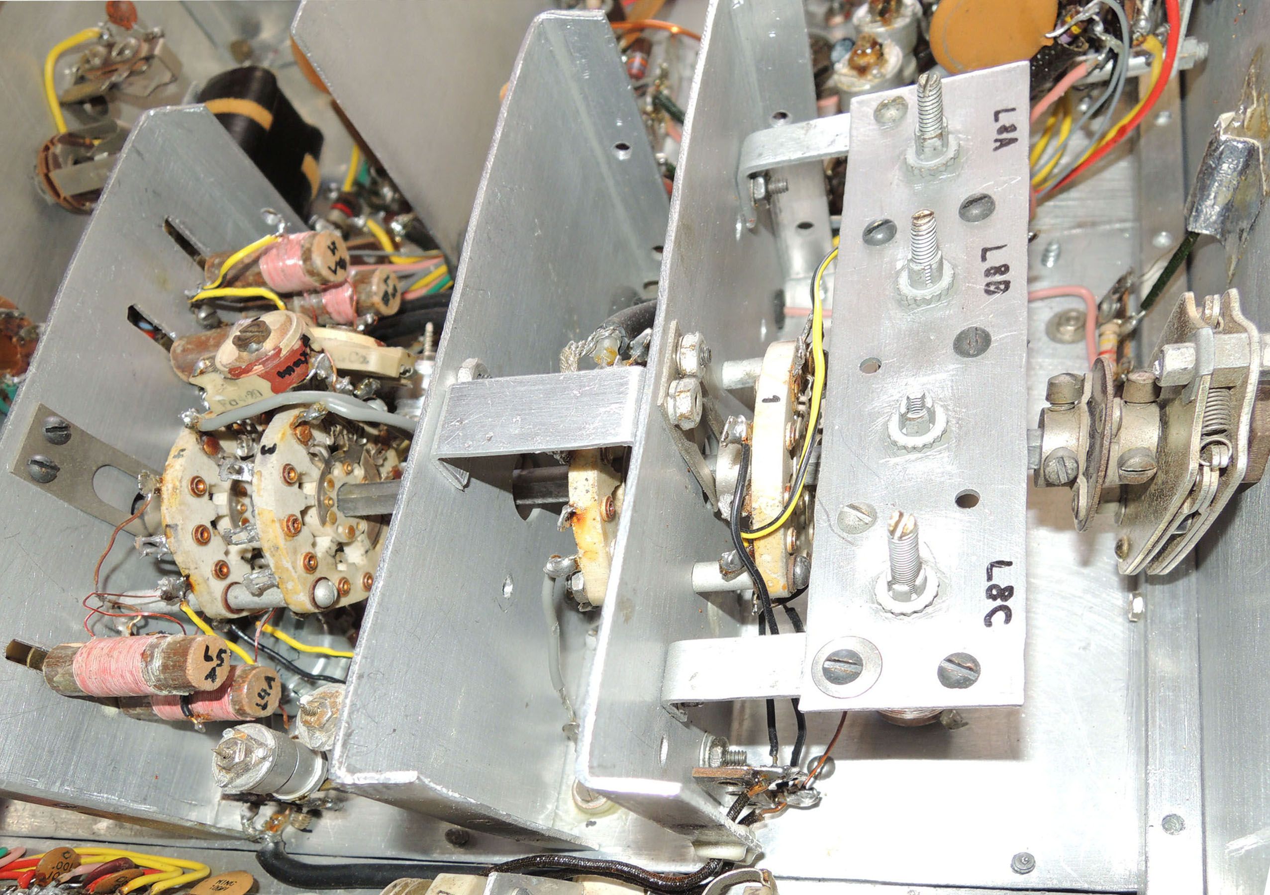
The band switch assembly and some of its coils. The adjustable coils under the plate on the right are surplus; the ones on the left I wound myself on shellacked wood dowels. Note the spring-loaded switch detent at the right end and the grounding spring at the left. As I said, this switch was a serious piece of bad-ass mil-grade WW2 hardware! |
|
|
|
 Click photo to enlarge |
|
|
|
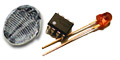
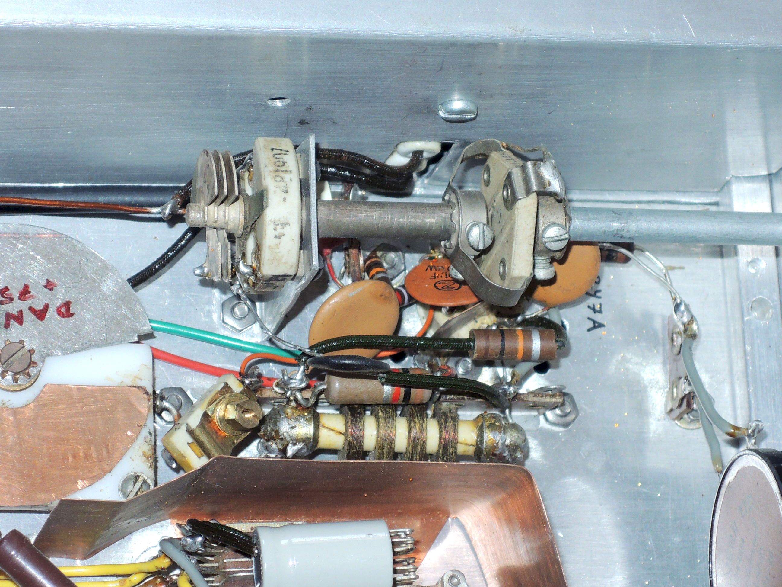
Without access to the US supply chain, anything ceramic I sighted at the “Junk” surplus store was a big deal; here you see three such finds: an RF Choke -- those were especially hard to come by in the values needed for ham gear -- and a ceramic-mounted variable capacitor with a ceramic-insulated shaft extension thingy (I forget what those were called). |
|
|
|
 Click photo to enlarge |
|
|
|
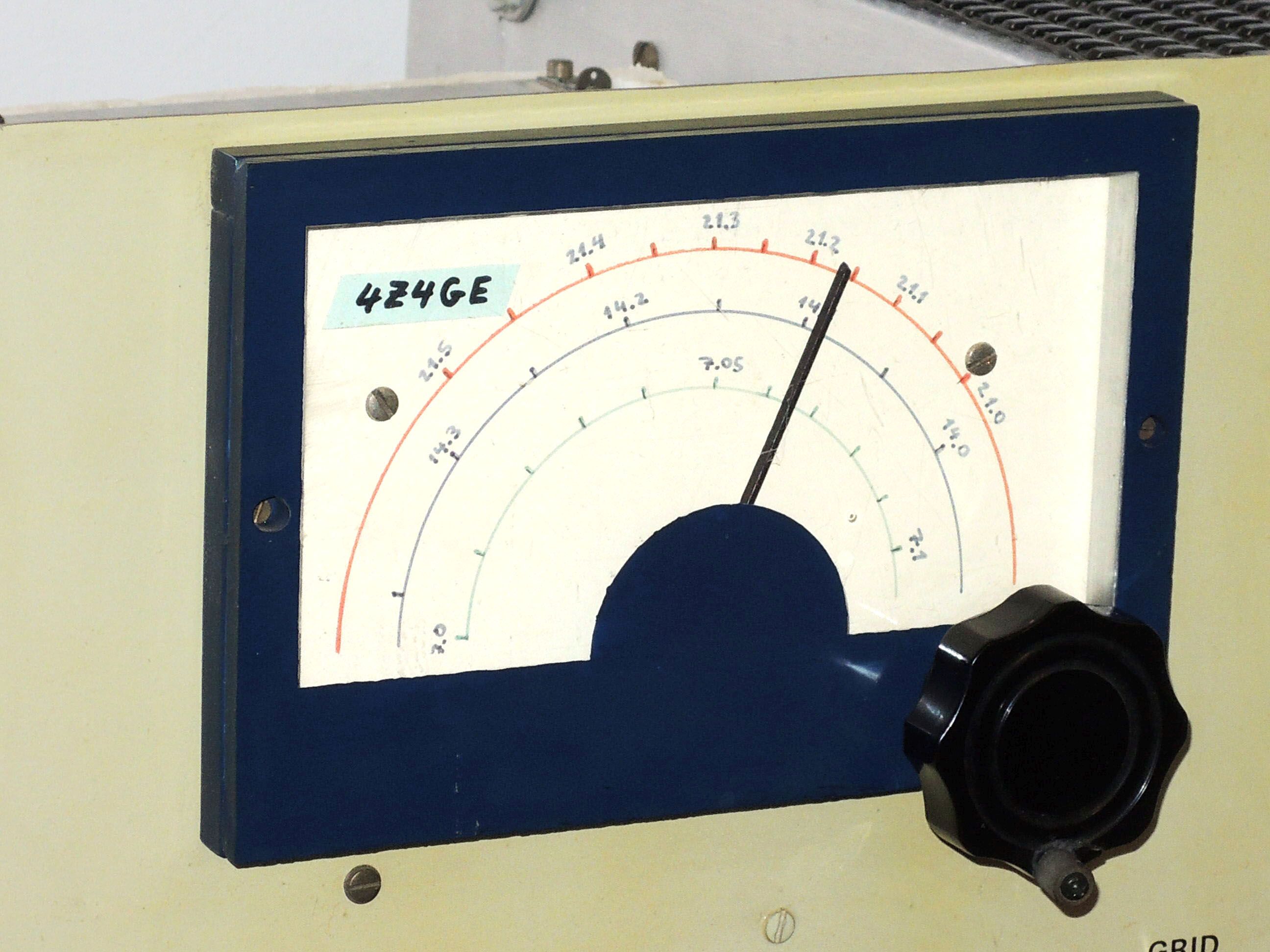
The construction articles in QST routinely used the slick dials from the James Millen and J.W. Miller companies. Since I couldn’t get those in Israel, I built this dial from Plexiglas, aluminum rods and blue paint. The reduction gear came already integrated into the ARC-5 variable capacitor inside, so I was spared having to develop that part too. |
|
|
|
 Click photo to enlarge |
|
|
|
The power supply used solid state rectifiers but still sported two gas-filled voltage regulator tubes. The smaller transformer seems to be a reclaim from some home radio receiver, but the larger high voltage transformer was wound to my specification by a local transformer manufacturer. |
|
|
|
 Click photo to enlarge |
|
|
|
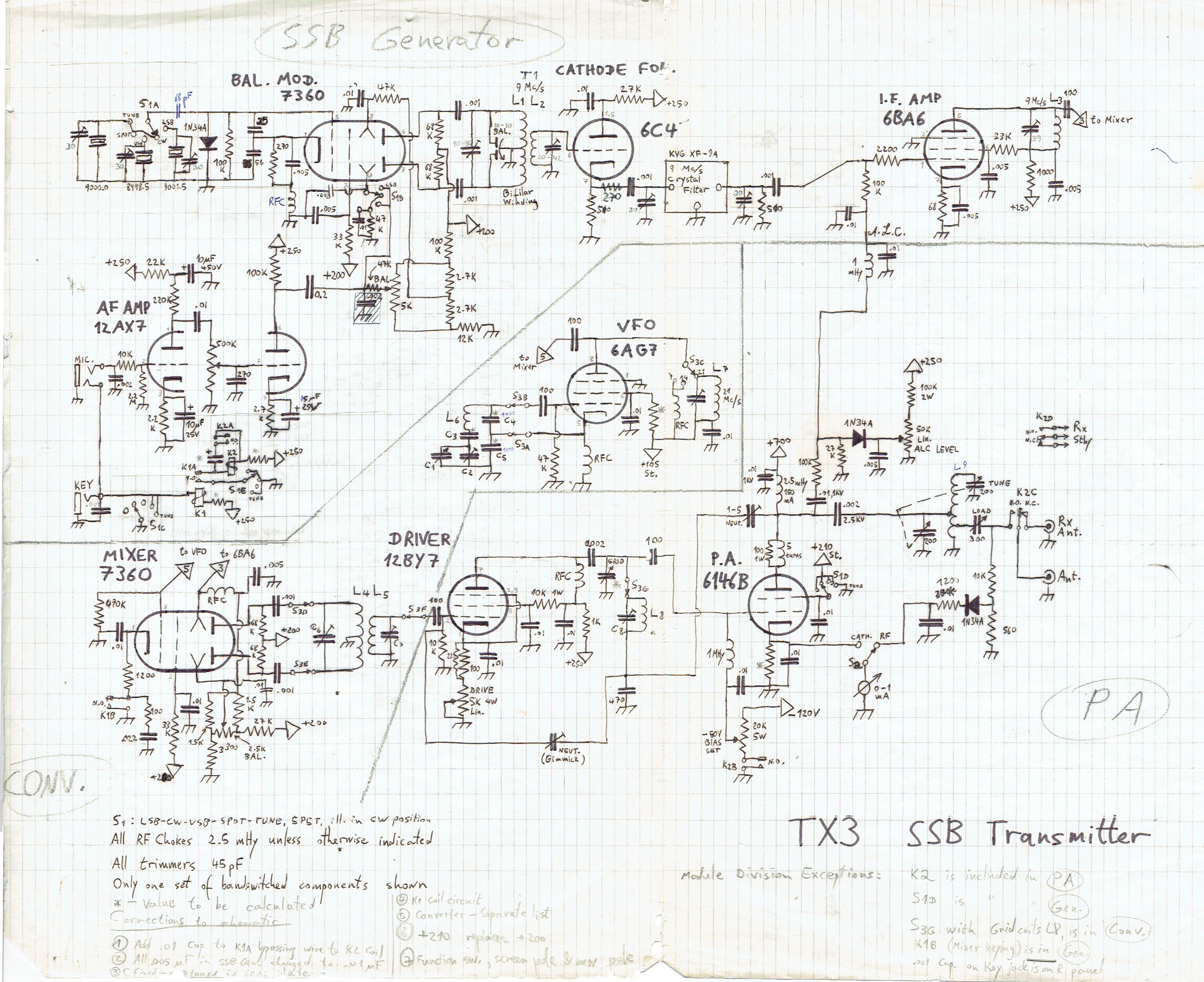
Here is the full schematic, with a few penciled in errata as the design evolved. |
|
|
|
 Click photo to enlarge |
|
|
|
Well -- that’s it. This transmitter was the
most ambitious homebrewing project I’d ever tackled (or possibly it
may tie with the oscilloscope that followed). It worked well -- no
competition for a Collins or even a Heathkit, but good enough for
all my practical communication needs. And of course it was huge fun
to build, which for me has always been the main thing... 73! |
|
|
|
|
|
|
|
Home | HOC | Fractals | Miscellany | About | Contact Copyright © 2018 N. Zeldes. All rights reserved. |
|